Wanos supports bridge mode by default. Bridge mode is the recommended design due to the simplicity and ease of deployment. Various high availability options are possible in bridge mode.
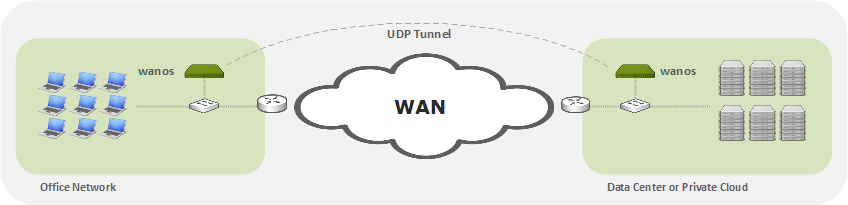
Alternatively in some cases tunnel mode can be considered. Tunnel Mode creates an IPComp or UDP tunnel to the destination Wanos instance. Routing is required to route the traffic destined for the remote site to the local Wanos instance.
When enabling Tunnel Mode, version 4 or higher is recommended.
How it works
Caveats
Requirements
Configuration
How it works
- Tunnel mode only use the physical wan0 interface. Disconnect lan0 if it exists.
- The wan0 gateway should normally be the wan router.
- The wan0 IP address is a gateway address for LAN devices.
- Workstations or Servers are configured with the wan0 address as their gateway address.
- Layer-3 switches can also be used to route traffic to the Wanos gateway.
- Traffic sent to Wanos will be validated for optimization based on the Tunnel Policy subnets and Traffic Policies
- From v.4 onward all traffic matching the tunnel policy will be encapsulated and tunneled to the remote destination peer.
- The traffic will be sent to the peer that match the destination subnets in the tunnel policy configuration.
- Once the traffic is received by the remote peer it will be de-encapsulated, de-optimized and forwarded to the default gateway.
- When enabling tunnel mode, all sites need to run tunnel mode
- Repeat the same steps and routing configuration at the remote peer sides.
Caveats
(v.3) Only optimized traffic is tunneled in version 3. Hence tunnel mode is not a VPN replacement in v.3. When running tunnel mode v.4 or higher is recommended.
Requirements
- Deployment mode needs to be tunnel mode at all sites.
- A single network interface is used.
- Firewalls need to permit IPComp or UDP 4050 depending on encapsulation configured.
- Configure the destination subnet and the destination Wanos Peer IP address in Tunnel Policies.
- Promiscuous or Mac-spoofing is not required. On Amazon AWS “Check source/destination” needs to be disabled. On Microsoft Azure, IP Forwarding needs to be enabled.
- For simple deployments sse Wanos as the default local gateway on LAN workstations. Alternatively use routing on the core switch or firewall to direct traffic to Wanos.
Minimal Configuration Steps
- Add the remote destination subnet(s) with the remote site Wanos peer IP in the Tunnel Policy configuration.
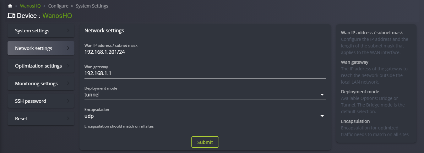
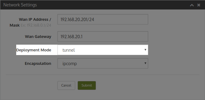
- In Network Settings, select Deployment mode: Tunnel. Click Apply
- Change gateways or add routes on test workstations on both sides, which are in the same subnet as the Wanos appliance, to use Wanos as gateway.
- Send TCP traffic between the two workstations and monitor the dashboard and peer status tabs.
Routing Requirements
- Traffic to be tunneled to the remote site needs to be routed to the local Wanos instance.
- For simple deployments change the gateway on the server or client workstation to use Wanos as the default gateway.
- Alternatively use specific subnet routes on the server, Layer-3 switches, firewalls or routers to channel traffic that needs to be tunnel to the local Wanos.
Verification
- Ensure gateways or routing rules have been configured at at both ends.
- Traceroute from both ends to confirm traffic is routed over the tunnel in both directions.
- To test that the tunnel is configured correctly, run a traceroute from the test workstation in site-A to test the workstation in site-B. Then repeat the traceroute from site-B to site-A to confirm the tunnel path is used in both directions.
- Once confirmed routing is working correctly, generate TCP traffic over the tunnel and monitor the Peer status tab to confirm Peers have automatically discovered each other.
Configuration Summary Steps
- Configure Hostname, IP address and Gateway (WAN Router).
- Configure Tunnel Policies that match remote subnets that need to be tunneled to match the remote Wanos peer IP.
- Switch Deployment to Tunnel under Network Settings.
- Configure Server-A in Site-A to use Wanos-A as default gateway. Or add this routing on the core switch at Site-A
- Configure Server-B in Site-B to use Wanos-B as default gateway. Or add this routing on the core switch at Site-B
- When using core switches to route traffic to Wanos, add routes on Wanos in order for the local Wanos to be able to reach the LAN subnets.
- Test non-bypassed TCP traffic between Server-A and Server-B (e.g. HTTP, FTP).
- After initial successful tests, if needed, consider more interesting routing options like policy based routing or setting routes via DHCP options.
Troubleshooting
When a layer 3 core switch is not available, firewalls are often used as the only routing device for both WAN and the LAN networks. When the firewall is the only route device for both WAN and LAN there is a possibility that the firewall will block traffic from the remote side due to asymmetric routing or firewall policies filtering. For example an optimized packet from a remote branch or cloud provider is sent over the optimized tunnel to the HQ Wanos. When the tunnel packet is received the tunnel header is stripped and the original source and destination IP header is exposed. The packet is then sent to the LAN, but since the Firewall is also the gateway to the LAN, the firewall receives the traffic sourced from the remote addresses on the inside. This traffic is often blocked to filtering rules or reverse path checks.
If a Layer 3 core switch is available, add route policies on Wanos to send traffic destined for the LAN directly to the core switch. This is also more efficient and may translate into higher throughput. When a core switch is not available for the LAN routing, reverse path check settings can be adjusted to allow the firewall to allow the traffic to pass.
Below is a Fortigate sample config to allow remote site traffic to be routed on the inside interfaces:
config system settings
    set asymroute enable
end
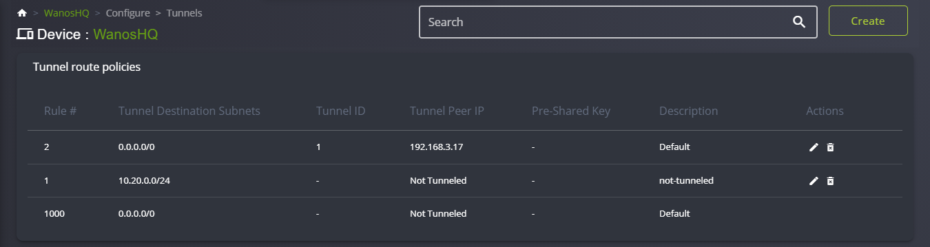
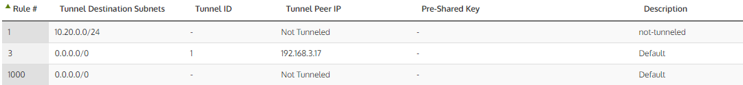
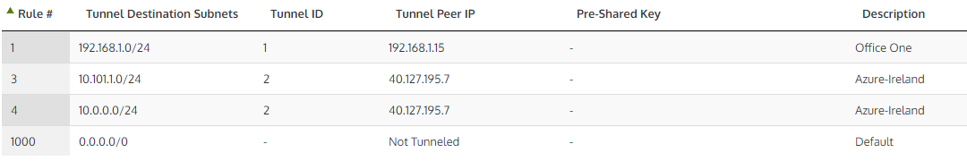
Tunnel Policy Examples:

Video Guide
Tunnel mode video guide.