Wan Optimization high availability or redundancy can be achieved by a number of methods. Please contact support to for a design recommendation.
1) Although Bridge Mode with a Bypass Network Interface card is the recommended setup for most deployments, high availability can also be achieved in Tunnel Mode by monitoring the gateway IP address. If the Wanos Gateway for whatever reason becomes unavailable, the Router automatically removes the policies to redirect traffic to Wanos. Below is a A sample IP SLA tracking config for Cisco devices for Tunnel Mode.
ip sla 1
icmp-echo 10.0.0.1
frequency 4
ip sla schedule 1 life forever start-time now
!
ip access-list extended to-wanop-tunnel
deny ip host 10.0.0.1 any
permit tcp 10.1.1.0/24 192.168.1.0/24
!
route-map wanop-tunnel-mode
match ip address to-wanop-tunnel
set ip next-hop verify-availability 10.0.0.1 1 track 1
!
interface fastEthernet0
description Wan-Optimization-Tunnel
ip policy wanop-tunnel-mode
!
2) In Bridge Mode, Wanos support Bypass Network Interface Cards that work without drivers by default. Certain Bypass Card Drivers are included in the Wanos image. In the case of a power failure or software issue, the Bypass Card will automatically bridge the wan0 and lan0 interfaces and pass all traffic through. Contact support for more information on Bypass Cards supported and Wanos Appliances with builtin Bypass support.
3) When Bypass cards are not available, high availability can be engineered by running a backup network cable parallel to the Wanos device:
When running RSTP the Wanos device is placed between two switches, connected via wan0 to the outside switch and lan0 to the inside switch. The backup link is cabled between the same two switches. Hence two cables run between the outside and inside switch. STP will elect a primary and secondary path based on the port id. Place the Wanos ports on the lower port number or configure the switch to make this link the primary path. RSTP should place the backup link in an alternative path status and will switch over to the backup link within a few milliseconds of detecting a loss.
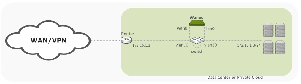
When running Per-Vlan RSTP high availability can be achieved using a single switch. In this case two VLAN’s are created. The Outside VLAN connects the WAN segment and the Inside VLAN connects the LAN segment. In the diagram below, the Router, Wanos wan0 and the backup link is connected to VLAN 10. On the LAN side the Wanos lan0, Data LAN segment and the backup link is connected to VLAN 20. Under normal conditions the Wanos device bridge traffic between the two segments and the backup link is passively idling. When the switch detects a failure on the primary path, the backup link is enabled and immediately placed in the forwarding state. Advance features like loop guard and hello timers can be adjusted to improve convergence times.
Example Cisco Switch Config:
spanning-tree mode rapid-pvst
interface range fa0/1 -3
description WAN
switchport access vlan 10
spanning-tree mode access
interface range fa0/4 - 6
description LAN
switchport access vlan 20
spanning-tree mode access
interface fa0/4
description Primary-Wanos
spanning-tree cost 1
Example diagram of enabling redundancy with a single switch: