Quick Cabling Guide
Connecting cables to the correct ports
User workstations and Servers connect to the lan0 network. The wanos appliances connect to the wan on the wan0 port.
Here are a few tips and tools to assist in the process:
- On default, eth0 would be assigned to wan0 and eth1 to lan0.
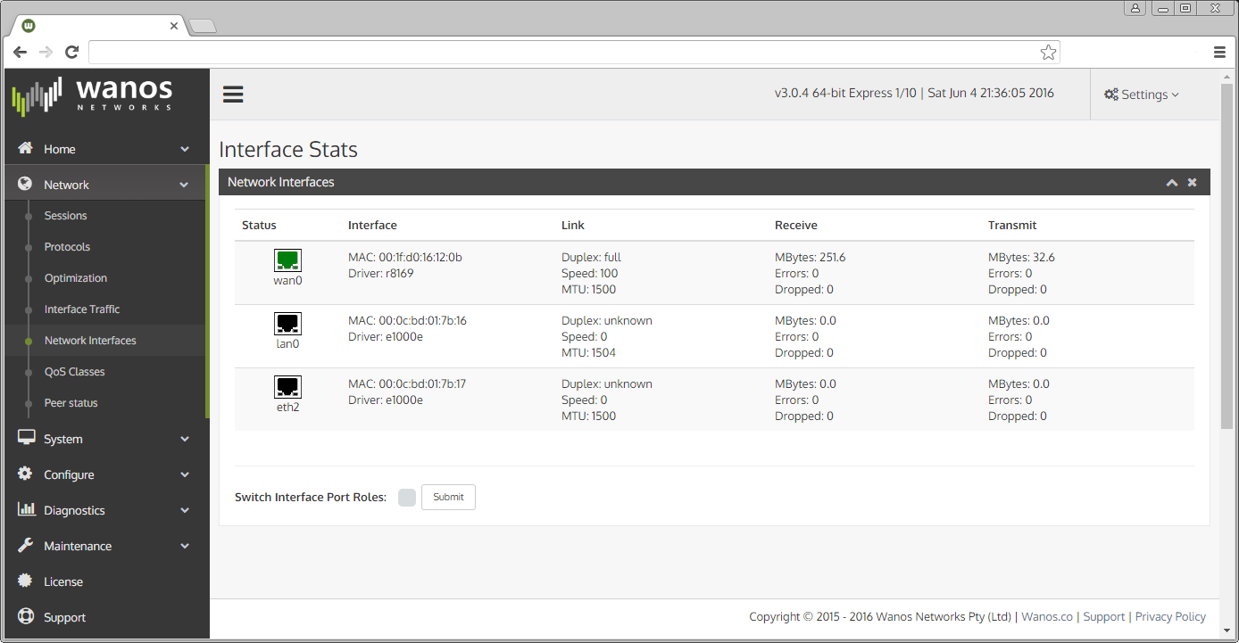
- The web interface displays a green indicator when a port is connected.
- If the log displays “Peer detected on lan0″, switch the ports roles on this appliance.
- In virtual environments the MAC address can be used to switch virtual interfaces.
Using the Web Interface
On physical appliances and hypervisors that emulate the physical network state, the web GUI will display the Ethernet port status. A green port indicates the interface has detected a network cable and is online. A black port indicates that a cable is unplugged. On first boot eth0 will be assigned to wan0 and eth1 to lan0. The GUI indicators can be used to identify the port roles and are useful in determining whether cables are swapped. If this is the case redo the cabling or use the “Switch Interface Port Roles” feature to align the cables with the correct roles. “Peer detected on lan0” notifications in the Edge log is another indicator that the port roles need to be switched.
Virtual Appliance Cabling
After the virtual appliances have been created the next step is to ensure the links are cabled correctly. The first Ethernet, usually eth0, will link to the WAN router. This interface will be the wan0 interface. The second Ethernet connects to the rest of the LAN and is called the lan0 interface. Together these two interfaces form the inpath pair. They are configured to bridge traffic and have no IP addresses.
When establishing a test lab it is also possible to use the Hypervisor ‘internal network’, ‘lan segments’ or ‘virtual networks’ to create the required network topology. For best results in production environments map a physical network interface for each lan0 and wan0 interface.
Switches
Traffic between lan0 and wan0 is bridged and therefore it is important that the bridge appliance is deployed between the WAN side of the network and the LAN side of the network. When Firewalls are part of the network, place the bridge appliance between the WAN Router and the Firewall. When the Firewall is also the WAN router, the wan optimization appliance needs to be placed on the lan side. Note that connecting both interfaces to the same switch can cause the switch to block one of the ports or worse create a bridge loop if STP is disabled. It is possible to safely connect both ports to the same switch only if the switch ports are configured in different VLAN’s and running Per VLAN Spanning-Tree Protocol (PVSTP).